
Figure 1. Fixed Angle Solar Panels.
This was a huge problem for our team so we resulted in creating our own frames out of wood shown in Figure 2.


Figure 2. Wooden Frame Panels
Instead of the fixed angle mounting assembly, we transitioned to an adjustable angle version. The objective of these designs was to allow the solar panels to move at any variable angle desired. From the fall semester, we concluded the maximum effective angle are from 30 to 60 degrees. This made an adjustable angle design was much more favorable for Maker's Faire. My team came up with two other designs with different variations. Either design can be slotted or make use of pin holes. There are pros and cons for each variation. The slotted variation allows better selection of angles but when the difficulty of fabrication is high. The other variation is the use of pin holes. When fabricating, accuracy is important and without making the use of the waterjet cutting machine, this wouldn't be possible. Figure 3 and Figure 4 shows the different variations of the first design. Using bolts, it will help ensure it to our desired angle. The first design required a lot of accuracy in fabrication due to the addition of the mounting cap.

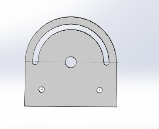
Figure 3. Slotted Circular Design

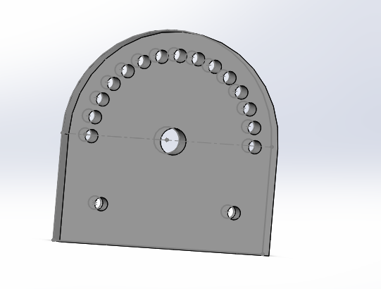
Figure 4. Pin holed Circular Design.
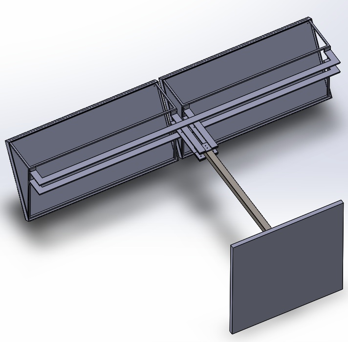
Our second design is a three bar mounting assembly shown in Figure 5. This can also be slotted if needed as shown in Figure 3.
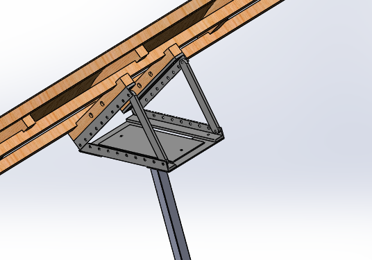
Figure 5. 3 Bar Mounting Assembly.
Mid-Spring Semester, we decided to fabricate the second design due to the simplicity of fabrication and in-house materials. Most of the materials use are going to be aluminum as they are lighter than steel. Using three pieces of aluminum, they are welded together and to be bolted on with the steel plate underneath shown in Figure 6. Underneath the steel, there is a five-inch rectangular tubing that serves as a mounting cap to the track post. With the amount of the weight of the solar panel frame and the 3 bar mounting assembly, my team believes that it will help stabilize the movement from the track post.
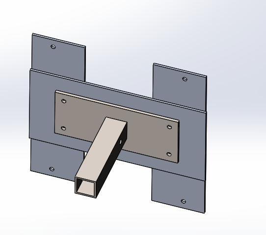
Figure 6. Bottom of the mounting assembly.
In Figure 7. shows how the entire the track will look once fabrication is done.
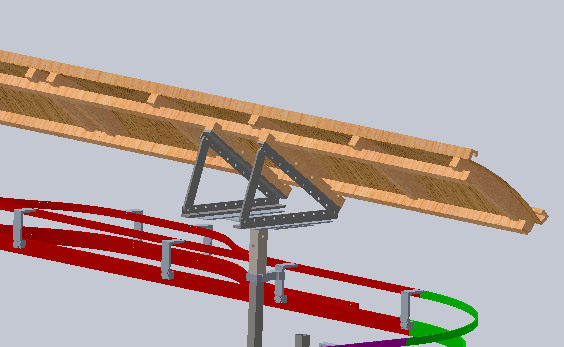

Figure 7. Projected completion.
No comments:
Post a Comment